BL-Touch Installing Guide for LK4PRO & LK5PRO
3d knowledge3D Printing knowledgelk4 prolk5 pro

BL-Touch Installing Guide for LK4PRO & LK5PRO

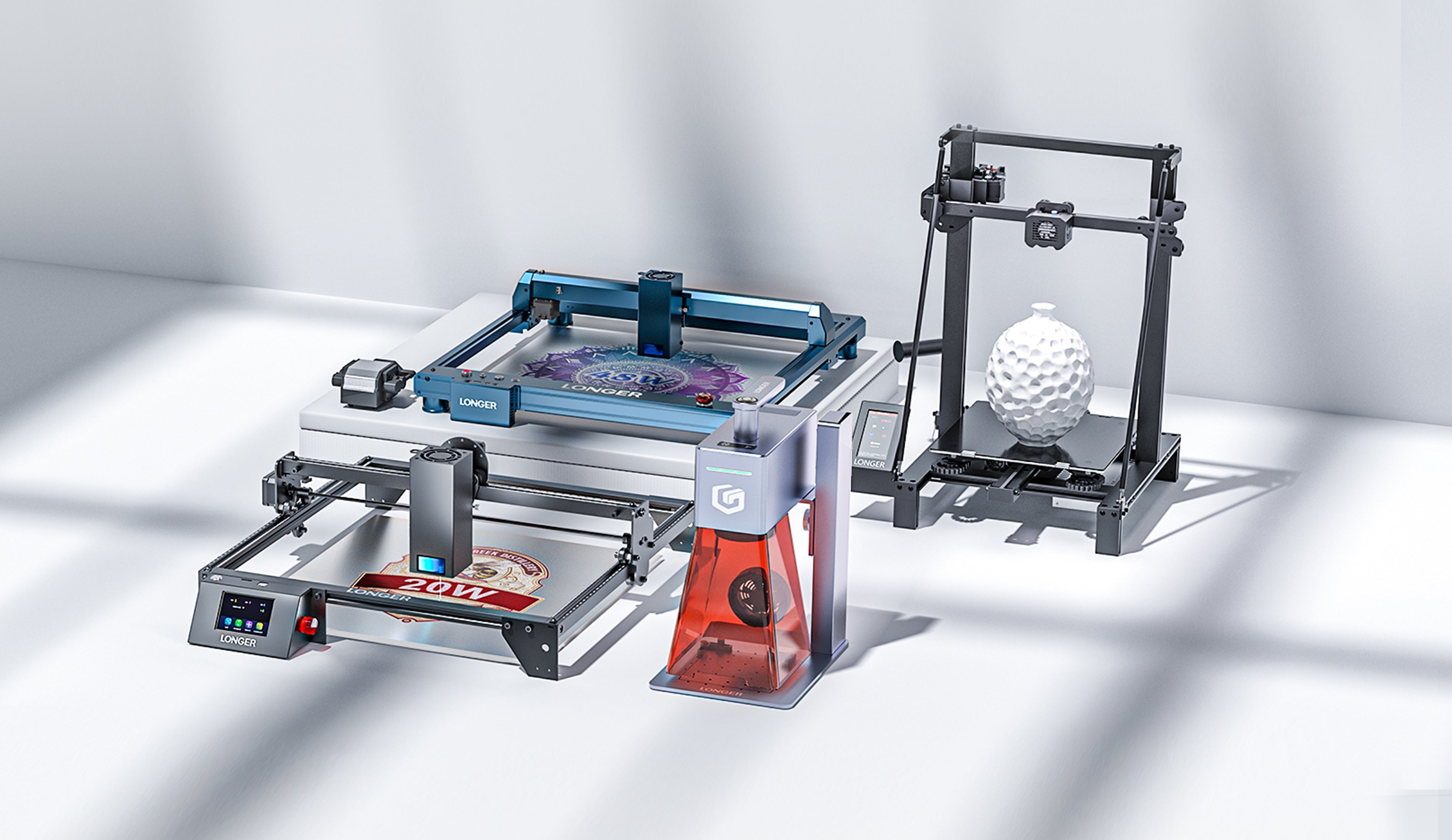
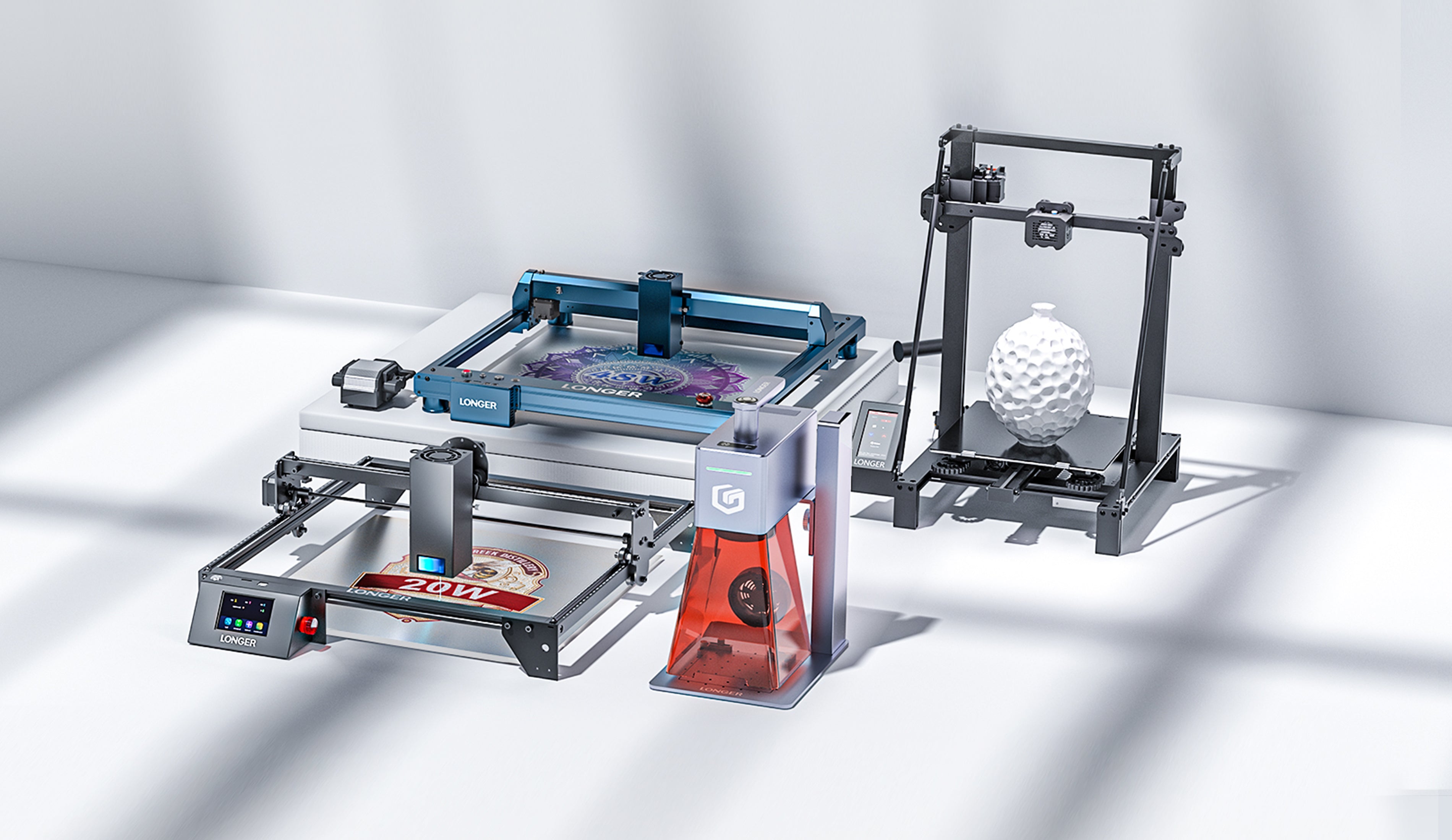
Longer LK4PRO & LK5PRO are two FDM printers capable of producing high-quality 3D prints. However, you can increase the ease and quality of printing by installing a BL-TOUCH or 3D-TOUCH compatible automatic leveling sensor.


Preparation

Wiring

  1. Switch-off the printer
  2. Find the position of motherboard, then screw down the mainboard cover
  3. Unplug the Z-MIN wire (2-pin) from the mainboard
  4. Connect the sensor's cables to the motherboard, as the picture below shows.
    Connect the sensor's cables to the motherboard
  5. Screw up the mainboard cover
  6. Remove the Z endstop switch, as picture showing below
    Remove the Z endstop switch
  7. Screw down the left 2 screws of the printhead module and mount the BL-TOUCH as picture showing below (follow the same step if you have DualBlower)
    Screwdown left 2 screws of PrintHead module and mount the BL-TOUCH

Configuration

  • Confirm BL-TOUCH wiring and mounting is complete
  • Power ON the printer
  • Connect PC and printer with the modified USB cable.
  • Open Pronterface software, select serial port (115200 baudrate) and connect it to the printer

Adjusting Z-Offset

  1. Clean up bed and nozzle, and ensure no materials stick on 
  2. Send M851 Z0 to reset Z offset value.
  3. Send G28 to home XYZ axis
  4. Send G1 F60 Z0 to lower Z axis to the software origin. 
  5. Send M211 S0 to inactivate software endstop function
  6. Place a sheet of paper (0.10 mm approximately) on the bed and use Pronterface to lower the nozzle 0.1 mm by 0.1 mm until you feel friction between the nozzle and the sheet of paper (the paper is not to be jammed but not too free either). Then remove the sheet
  7. Send M114 to get the current Z height value (usually negative) and take note of it. This is the z-offset value we need
  8. Send M851 Z-x.x to set z-offset. (x.x is the value of previous value; for example, if previous value is -1.2, then send M851 Z-1.2.)
  9. Send M500 to save current settings
  10. Send M211 S1 to reactivate software endstop function. 
  11. Send G28 to home XYZ axis
  12. Send G1 F60 Z0 to test if the Z axis could go back to the actual Z origin by checking the clearance between the bed and the nozzle if it is about 0.1 mm (the thickness of a sheet of paper). If not, please repeat steps from 1 to 11.

START GCODE replacement

Inside the Slicer software (Cura, Slic3r, Simplify3D), replace the original START GCODE with the following START GCODE for BL-TOUCH.

-- BL-TOUCH START GCODE --
G21; metric values
G90: absolute positioning
M82: Set extruder to absolute mode
M107: start with the fan off
; confirm BL-touch safety
M280 P0 S160 ; BL-Touch Alarm release
G4 P100 ; Delay for BL-Touch homing
G28 X0 Y0 ; move X/Y to min endstops
G28 Z0 ; move Z to min endstops
; reconfirm BL-touch safety
M280 P0 S160 ; BL-Touch Alarm Release
G4 P100 ; Delay for BL-Touch
; bed leveling
G29: Auto leveling
M420 Z5 ; set LEVELING_FADE_HEIGHT
M500: save data of G29 and M420
M420 S1 ; enable bed leveling
; prepare hot-end
G92 E0 ; Reset Extruder
G1 Z2.0 F3000 ; move the Z Axis up little to prevent scratching of the heat bed.
G1 X0.1 Y20 Z0.3 F5000.0 ; Move to start position

G1 X0.1 Y150.0 Z0.3 F1500.0 E15 ; Draw the first line

G1 X0.4 Y150.0 Z0.3 F5000.0 ; Move to side a little

G1 X0.4 Y20 Z0.3 F1500.0 E30 ; Draw the second line

G92 E0 ; Reset Extruder

G1 Z2.0 F3000 ; move the Z Axis up little to prevent scratching of the heat bed.

G1 X5 Y20 Z0.3 F5000.0 ; Move over to prevent blob squish
; -- end of BL-TOUCH START GCODE -- 

Leave a comment

Please note, comments need to be approved before they are published.