Blog de grabador láser

Lubricating and Maintaining Moving Parts — Nano

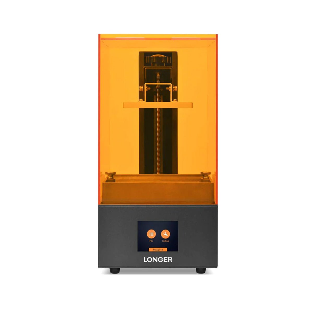
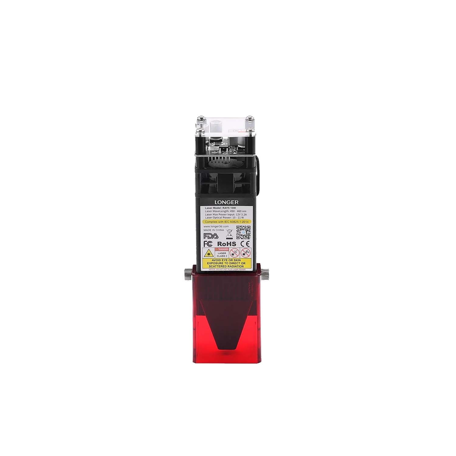
To lubricate and maintain the moving parts, follow these steps:

Remove the L-shaped support bracket

Turn the hand-tightened nut counterclockwise to remove the L-shaped support bracket.

Remove the column housing

1. Use a hex wrench to remove the 12 screws on the inner and outer sides of the column.

2. Remove the positioning plate and column cover to take out the column housing.

Remove the slider screws

1. Use a hex wrench to remove the 8 screws at the front and back that fix the slider in place.

Apply lubricant to the guide rails

1. Push the slider to one end of the guide rail.

2. Use a brush to apply lubricating oil to the contact surfaces of the guide rail.

3. Push the slider to the other end and apply oil again, ensuring an even distribution of lubricant along the contact surfaces.

Reassemble and clean

1. Wipe off any excess lubricant around the guide rails.

2. Refix the slider with screws.

3. Reinstall the column housing, positioning plate, column cover, and L-shaped support bracket in order.
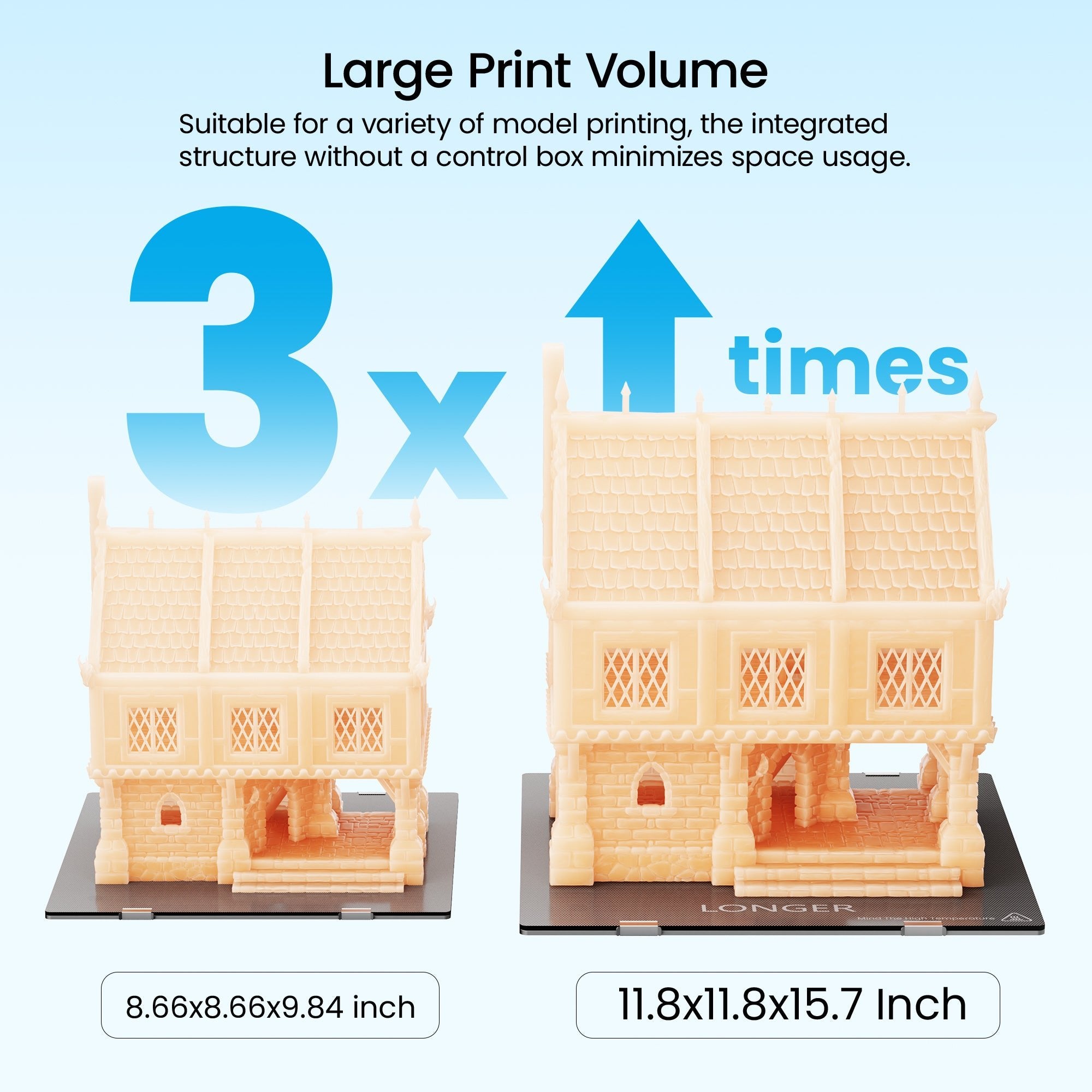
The lubrication and maintenance of the moving parts are now complete.

By Blog de grabador láser | November 13, 2025
Coupling Replacement for Nano

To replace the coupling, follow these steps:

Remove the L-shaped support bracket

1. Turn the hand-tightened nut counterclockwise to remove the L-shaped support bracket.

Remove the column housing

1. Use a hex wrench to remove the 12 screws on the inner and outer sides of the column.

2. Remove the positioning plate and column cover to take out the column housing.

Remove the old coupling

1. Use a hex wrench to remove the 2 screws fixing the coupling and the 8 screws at the front and back of the slider.

2. Once the connected moving parts are loosened, the coupling can be removed.

Install the new coupling

1. Place the new coupling in its original position.

2. Use screws to secure the coupling to the slider.

Reassemble the column housing

Place the column housing, positioning plate, and column cover back in order and secure them with screws using a hex wrench.

Reinstall the L-shaped support bracket

1. Reattach the L-shaped support bracket.

The coupling replacement is now complete.

By Blog de grabador láser | November 13, 2025
“Cut May Exceed Boundaries” Warning — Nano Troubleshooting

The “Cut may exceed boundaries” warning usually occurs for the following two reasons:

1. Pattern Position Exceeds Engraving Area

If the pattern is positioned outside the engraving area, adjust its location on the canvas to ensure it is fully within the workspace.

LightBurn:

Change the XPos and YPos parameters in the top menu bar.

LaserBurn:

Adjust the X and Y parameters under Position in the top menu bar.

2. Pattern Size Exceeds Engraving Area

If the pattern’s size exceeds the engraving area, resize the pattern so that it fully fits within the workspace.

LightBurn:

Adjust the Width and Height parameters in the top menu bar.

LaserBurn:

Modify the W and H parameters under Size in the top menu bar.

By Blog de grabador láser | November 13, 2025
Transferring Images to the LaserBurn App on Nano

There are two methods to transfer images from a computer to the LaserBurn app:

SD Card Transfer:

1. Save the image to an SD card using a card reader.

2. Insert the SD card into the laser engraver.

3. In the LaserBurn APP, go to the relevant module and view the files on the SD card. This completes the transfer of the image from the computer to the LaserBurn APP.

 Using Third-Party Software:

1. On your computer, send the image to a third-party software that can sync data between your computer and smartphone.

2. Log in to that software on your phone and save the image.

3. The image can then be used within the LaserBurn APP.

By Blog de grabador láser | November 13, 2025
Blurry Engraving Patterns — Nano Troubleshooting

If the engraved patterns appear blurry, you can address it using the following methods:

1. Adjust Speed and Power

LightBurn:

Go to Cuts/Layers, and double-click the layer you want to engrave.

Adjust the Speed and Max Power parameters, then click OK.

LaserBurn PC:

Click Layer, and select the layer to be engraved.

Adjust the laser power and speed parameters, then click Save.

2. Change Image Mode

LightBurn:

Go to Cuts/Layers, and double-click the layer you want to engrave.

Change the image mode to a suitable option, then click OK.

LaserBurn PC:

Click Layer, select the layer to be engraved.

Change Image Mode to a suitable option, then click Save.

3. Adjust Image Parameters

LightBurn:

· Select the pattern to be engraved.

· Press Alt+I or right-click and choose Adjust Image.

· Modify Contrast, Brightness, and Gamma, then click OK.

LaserBurn PC:

· Click the pattern to bring up the parameter adjustment window.

· Modify Brightness, Contrast, and Gamma as needed.

4. Change Engraving Material

If the material itself does not produce clear results, consider using a different material better suited for laser engraving.

By Blog de grabador láser | November 13, 2025
How to Fix Engraving Stutter on Nano Pro

The Nano Pro is a high-speed engraving machine, which can cause stuttering if the data transmission speed is slower than the engraving speed. To prevent stuttering, you can use the following settings:

Note: Engraving from an SD card will not cause stuttering.

LightBurn

1. Click the relevant button in the top menu bar and enable the Enable GCode Clustering option.

2. Click OK to save.

LaserBurn (PC)

1. Click the relevant button in the top menu bar to open the Machine Settings interface.

2. Enable the Enable GCode Clustering option.

3. Click Save to apply the settings.

By Blog de grabador láser | November 13, 2025
Setting Image Engraving Position in LaserGRBL — Nano Pro

The zero point of Nano Pro is at the lower left corner. If you want

To engrave the file in the center, you need to set the offset.

Offset x=80-(Size_W/2);

Offset Y=70-(Size H/2);

By Blog de grabador láser | November 13, 2025
“Busy/Paused” Machine Prompt — Nano Troubleshooting

If the machine shows a “Busy/Paused” message, first check whether there is a process currently running in the APP, such as framing or engraving. If so, pause that process.

If no process is running, there are two possible solutions:

1. Check Driver Installation:

Ensure the installed driver matches your operating system.

If the driver is incorrect, the machine may show “Busy/Paused.”

Reinstall the correct driver.

2. Confirm USB Connection to Nano Pro:

Make sure the machine is successfully connected via USB.

Select the correct COM port (check Device Manager → Ports for the one with CH340 driver).

Ensure the port is not occupied by other software.

Once connected successfully, the console should display board information.

By Blog de grabador láser | November 13, 2025
No Laser Output During Framing — Nano Troubleshooting

When the laser does not emit light during framing, there are mainly two possible causes:

1. Lens Cover Not Removed
Remove the lens cover from the Nano Pro laser engraver.

2. Laser Not Enabled
When using LightBurn, click the top menu button and enable the “Laser on when framing” option, then click OK.

By Blog de grabador láser | November 13, 2025
Z-Axis Lifting Malfunction Fix for Nano

If the Z-axis lifting fails, you can replace the column control board by following these steps:

1. Remove the L-shaped support bracket

Turn the hand-tightened nut counterclockwise to remove the L-shaped support bracket. 

2. Remove the column housing

Use a hex wrench to remove the 12 screws on the inner and outer sides of the column.

Remove the positioning plate and column cover to take out the column housing.

3. Disconnect and remove the column control board

Disconnect the cables on both sides of the column control board.

Use a hex wrench to remove the 4 screws fixing the column control board.

4. Remove the rear screws

Remove the 2 screws on the back of the column control board to fully take it out.

5. Install the new column control board

Place the new column control board in its original position.

Secure it with screws and reconnect all the cables as they were originally.

6. Reassemble the column housing

Place the column housing, positioning plate, and column cover back in order.

Use a hex wrench to secure all screws.

7. Reinstall the L-shaped support bracket

Reattach the L-shaped support bracket. The Z-axis control board replacement is now complete.

By Blog de grabador láser | November 13, 2025