


The FDM 3D printing consists of a series of layers of molten material placed on top of each other; in this way, complex objects are created through a succession of layers. However, often some layers must be placed in areas without a base, so the layer is printed literally in a vacuum and it will inevitably fall down, but to overcome this problem it is possible to use supports, which act as a temporary scaffolding and can be removed once the print has been completed.
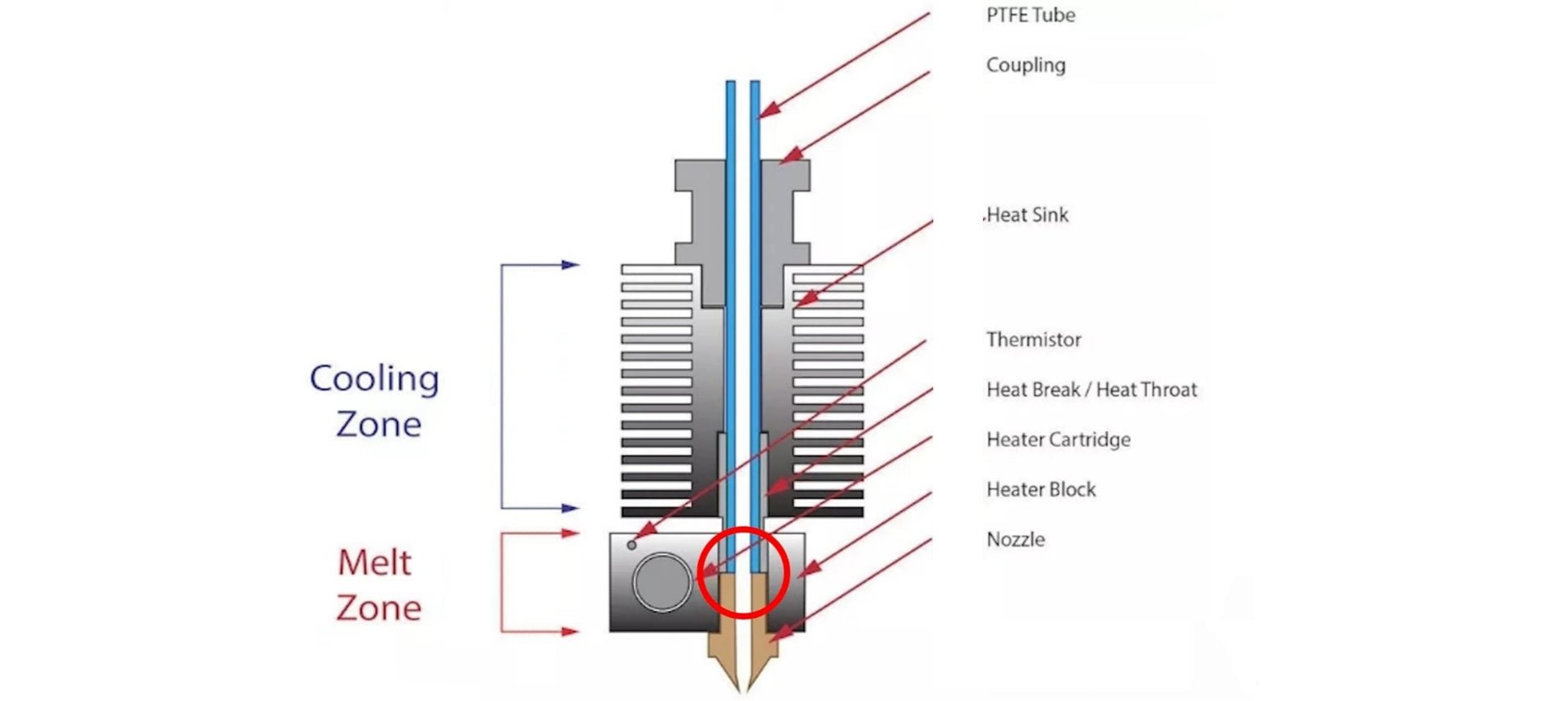
In some special cases it is possible to print suspended layers, without the use of supports. It may seem like an impossible feat, but over short straight distances you can print in a vacuum by instantly solidifying the layer using the air from the printer fans, thus creating a solid connection. This phenomenon is called Bridging and can be accomplished by means of some key print settings, such as flow, print speed and cooling.
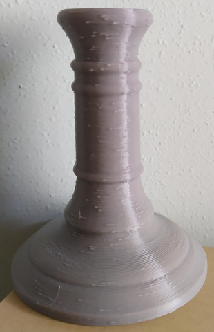
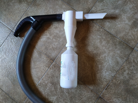
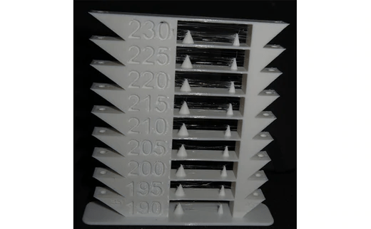
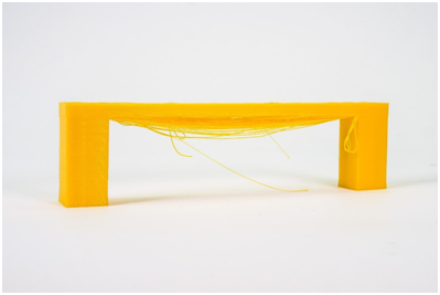
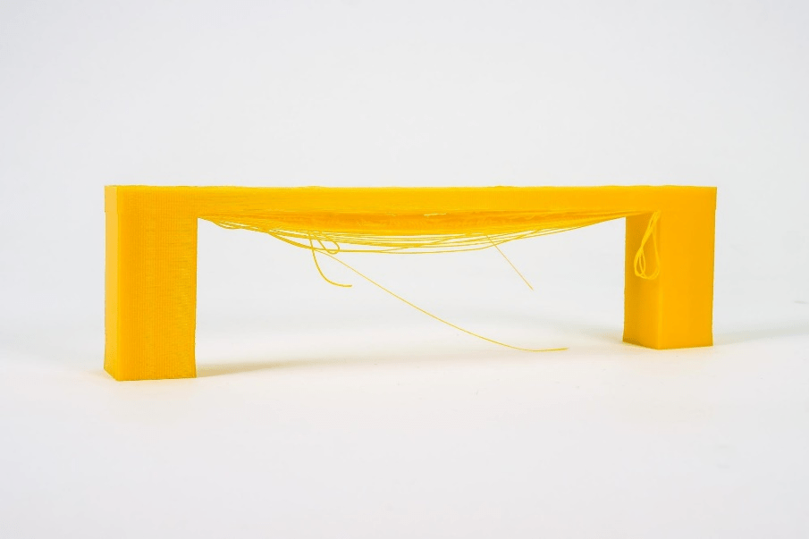
Depending on the settings used, the solidification of the layer may occur too slowly, thus causing it to sagging or lowering, as seen in the following photo.

By the way, below are some tips on how to improve bridging printing.
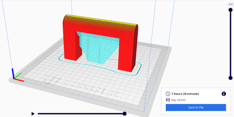
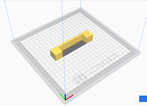
For tests you can download this sample, which can be printed several times depending on the settings chosen, until you find a satisfactory result:
https://www.thingiverse.com/thing:476845
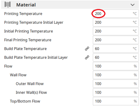
First you need to make sure that the print stream has been calibrated correctly; in this regard, it is possible to consult the previous lesson, relating to the "Printing Flow Calibration".
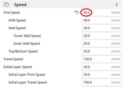
At this point, proceeding with the printing of the sample, if the bridging has unsatisfactory quality, it is possible to decrease the printing speed; progressively reducing the speed by about 5 mm/s it is possible to carry out various tests, until the ideal value is found.

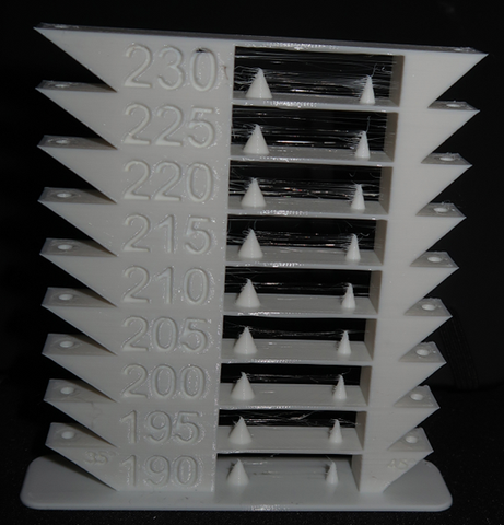
Printing temperature also plays a key role in bridging; in fact, the hotter the layer, the longer it takes for its solidification, thus causing a sagging. For this reason, by progressively reducing the printing temperature by about 5 ° C it is possible to carry out various tests, until the ideal value is found.

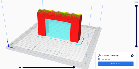
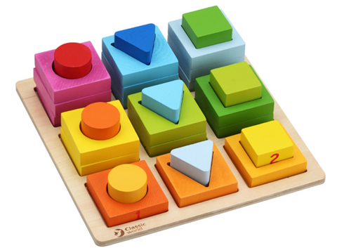
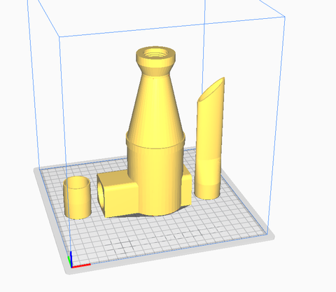
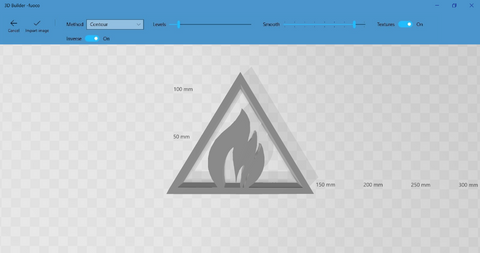
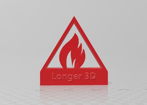
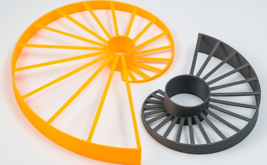
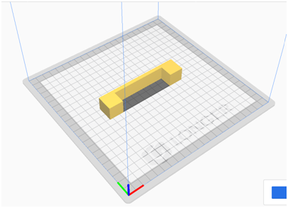
If the bridge is very long and the geometry of the object allows it, it is often possible to rotate the object until the suspended part disappears completely, as shown in the figure. However, in most cases this is not possible (including the case of printing the sample), so it is a solution that can be counted on very rarely.
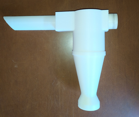
Longer Dual Blower Kit
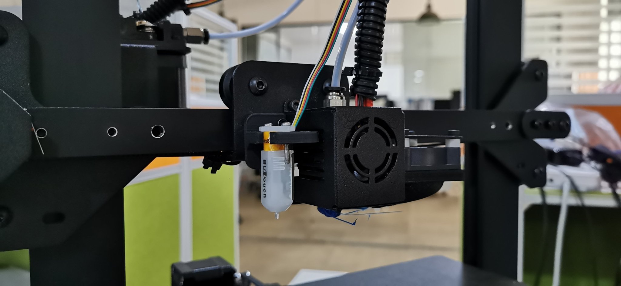
As mentioned from the beginning, for bridging the quality of air emitted by the cooling fan is fundamental, which must be able to instantly solidify the layer; for this reason, if changing the slicing settings is not enough, then the new Longer Dual Blower can help.
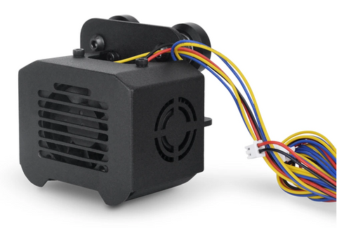
The new Longer Dual Blower has been specially designed to allow a faster and more uniform emission of cooling air, thanks to two bilateral turbo fans and a double ventilation duct; in this way the prints are much more detailed and the bridging printing greatly improved.
The installation is very simple, and can be done by consulting this video guide: https://youtu.be/zEA-eM5sfho
The purchase is available on the Official Longer Store:
https://www.longer3d.com/collections/accessories/products/longer-new-dual-blower-fan-kit
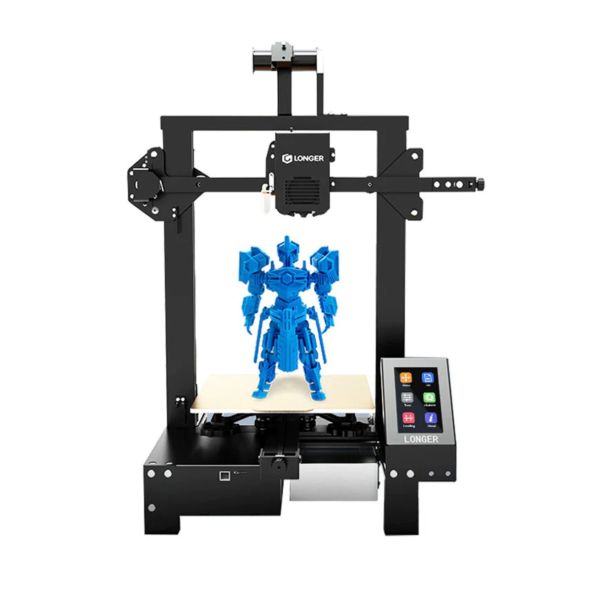
https://www.longer3d.com/products/lk5-pro-fdm-3d-printer