Academy

Introduction to the principle, development history and application of 450nm blue lasers - LONGER
Introduction to the principle, development history and application of 450nm blue lasers

The development of industrial laser technology has always followed the roadmap of production technology and new social requirements. Over the past 60 years, laser technology has made great contributions to solving important tasks in the future of mankind, from digital economy and society, to sustainable energy, to healthy life. Among them, blue-light laser refers to a laser with a wavelength in the range of about 400nm-500nm. Industrial-grade blue-light laser is generally a semiconductor laser.


Semiconductor lasers, also known as laser diodes, are lasers that use semiconductor materials as their working material. Semiconductor lasers take electric injection semiconductor lasers as an example. GaN, GaAS and other materials are usually added to the semiconductor material to make a semiconductor junction diode.

When a large enough current is injected into the diode, the electrons (negatively charged) in the middle active region It will spontaneously recombine with holes (positively charged) and release the excess energy in the form of photons, which will then be amplified by multiple reflections in the resonant cavity to form a laser.

Basic structure of semiconductor laser

Basic structure of semiconductor laser

Among them, in addition to the common characteristics of lasers, semiconductor lasers also have the advantages of small size, low driving power current, high efficiency, long life, easy optoelectronic integration with various optoelectronic devices, and compatibility with semiconductor manufacturing technology for mass production. They are favored by extensive attention and research from various countries. It has become the fastest growing, most widely used, the first to be commercialized out of the laboratory and the largest output value of lasers.


In terms of optical storage optical discs, because the possible recording and reproducing capacity is inversely proportional to the square of the light source wavelength, for example, an optical disc prepared using a 650nm red light semiconductor laser can record 4.7GB, while using 430nm blue light can store 4.7GB. The capacity has been increased to 15GB, so to achieve high density of optical storage, it is necessary to shorten the wavelength of the laser light source. In addition, blue-ray laser has the characteristics of short wavelength, small diffraction effect, and high energy. It has broad application prospects in material processing, optical information storage, display technology, communication technology, laser medical treatment, etc. The radiation wavelength of the semiconductor laser is determined by the bandgap width of the active area material.

Therefore, in order to meet the needs of miniaturization, low power consumption, high reliability and low cost, the use of GaN semiconductor materials has become the best choice for preparing blue lasers.


Therefore, at the 1997 GaN International Conference held in Japan, Nichia announced that the working life of the room-temperature continuous lasing blue laser had exceeded 10,000H. Major companies and powerful universities and research units in the world have invested in research and have successively achieved major achievements. breakthrough. In October 1999, GaN laser was commercialized with output characteristics of 5mW, wavelength of 400nm, operating current of 40mA, operating voltage of 5V, and a lifespan of 10,000h at room temperature, becoming a milestone in the development of GaN. In 2001, Nichia prepared a 150mW laser.


Early bluet lasers were low-power and did not gain much attention. Until recent years, with the marketization of single-tube blue TO packages, prices have been reduced, power has been increased, and various industrial manufacturing and fiber coupling technologies have been continuously enriched. People have realized the feasibility of developing high-power blue lasers.

Nichia NUBM44 Blue Laser Diode
With the winning of the Nobel Prize in Physics in 2014 and the increasing awareness of global environmental protection, GaN light-emitting devices have received widespread attention, especially in the field of lighting. By continuously improving the high brightness and high output of blue light semiconductor devices, blue light semiconductor lasers have entered the era of mass production. But for laser processing, higher power than the blue laser used for these lightings is required. Since blue-light lasers have many advantages as mentioned above, people have been working hard to develop high-power blue-light lasers for laser processing.

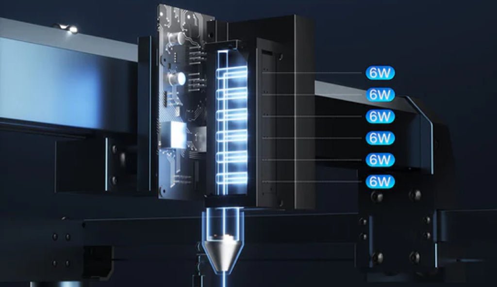
So far, the actual power of each chip of a blue semiconductor laser is about 5W at a single wavelength, so beam combining technology that combines the output of multiple chips is essential to obtain higher power output.

The first method is to use laser bar technology, which is to systematically generate a laser single chip (Single Emitter) on a wafer of semiconductor material. First, multiple individual laser chips are efficiently integrated into a so-called laser bar. Each laser bar can produce at least 50W of blue light. Then, through appropriate electrical connections, cooling and heat dissipation, and the use of special optical devices, multiple semiconductor laser bars are installed and combined into a semiconductor laser stack (Stack). The entire semiconductor laser can be composed of one or several semiconductor laser stacks. Currently, laser bar technology can reach 2kW blue light power.
Beam synthesis using semiconductor laser bar technology
The second method is to use semiconductor laser single tube (Single Emitter) technology, that is, each laser single tube is collimated with its own dedicated lens, so that the combined beam divergence can be kept as unchanged as possible and the beam divergence can be minimized. , thereby increasing the brightness of the laser. Current laser single-tube technology produces the best beam quality currently capable of reaching 1.5kW output power, which can be used in battery, electric vehicle and consumer electronics manufacturing.
Semiconductor laser single tube technology beam synthesis
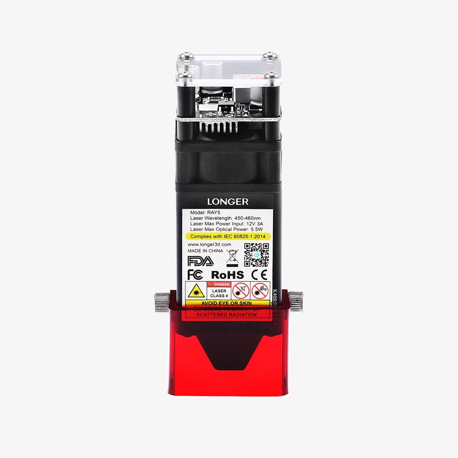
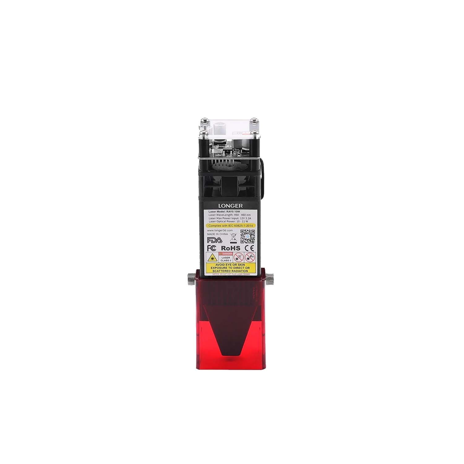
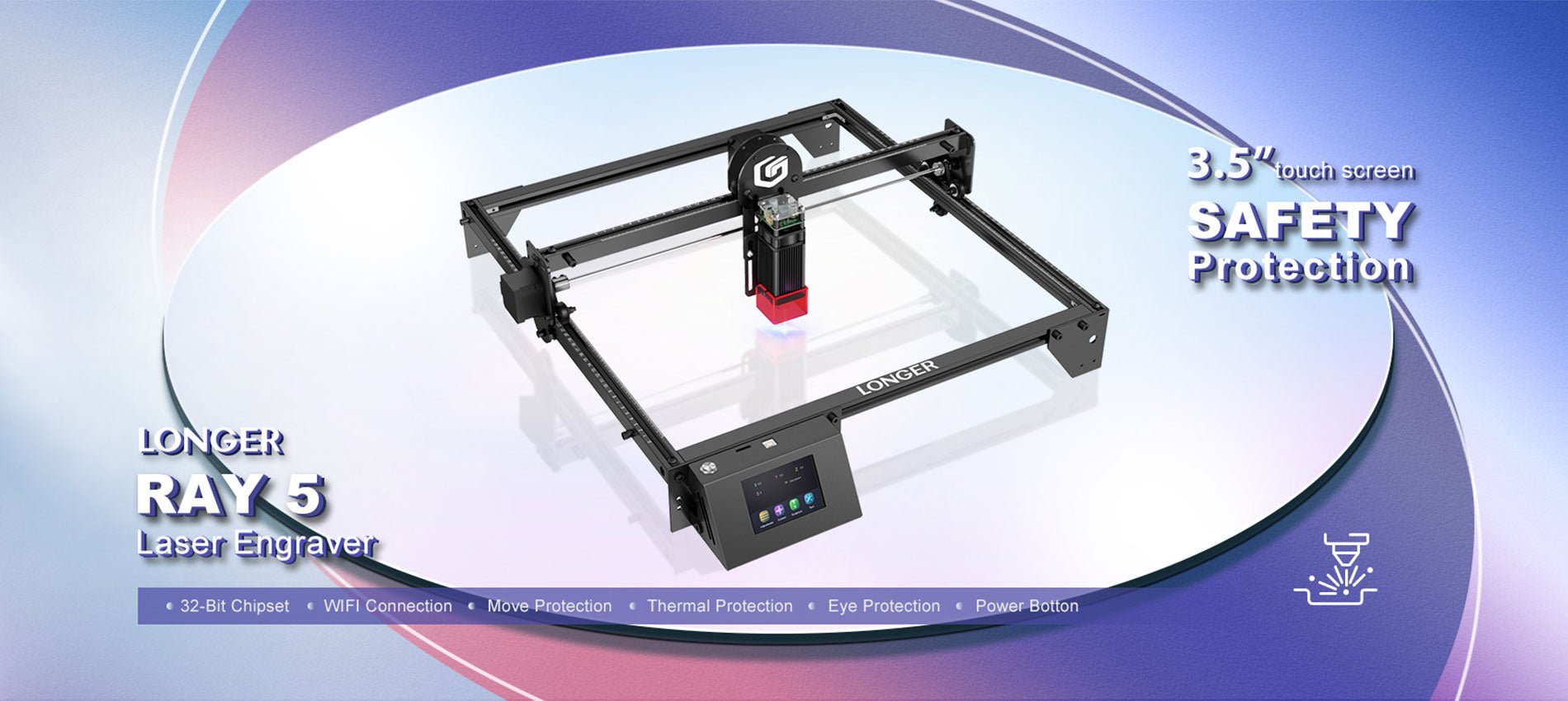
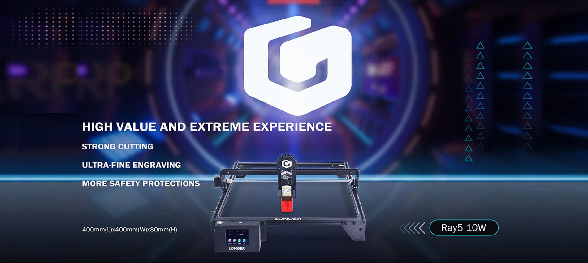
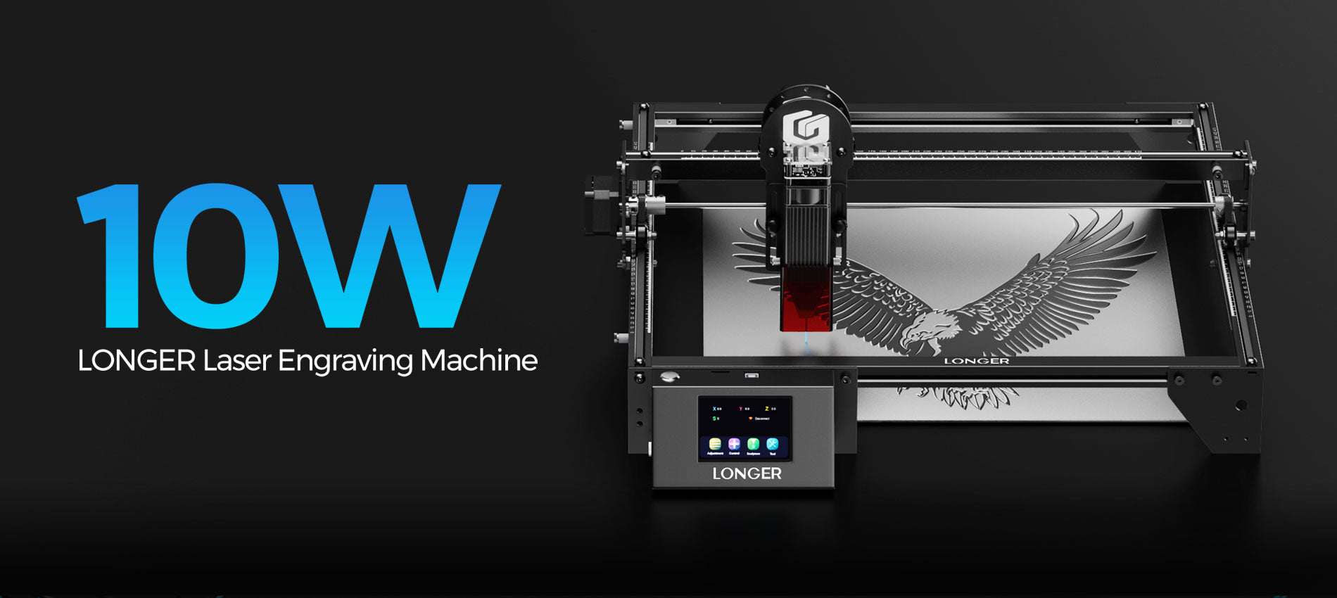
Benefiting from the high efficiency and absorption rate of blue light with a variety of materials, consumer-grade laser engravers, such as LONGER RAY5 and B1 series, have been widely used in the processing of wood, metal, food, acrylic, ceramics and other materials.

Laser Engravers on Wood: For wood and wood-based materials, the blue laser engraver offers the best performance. The blue laser engraver has the efficiency of 20-25% and, based on the available research papers, blue 445-450nm wavelength has the absorption rate of 68% and 73% on pine wood and beech wood respectively. A CO2 laser engraver has an overall energy efficiency of 5% and its wavelength has the absorption rate of 85% and 88% on the same two materials. Hence, a blue laser engraver is approximately 3.4 times more efficient than a CO2 laser at the same power consumption.

Laser Engraving on Leather: Academic research has shown that the absorption rate of blue laser wavelength stands at 88% for a blue laser beam and approximately 38% for a 1.06µm infrared fiber laser beam. Hence, a blue laser engraver is approximately 2.3 times more efficient than a 1.06μm infrared laser at the same laser power, which guarantees that a blue laser engraver will perform better in leather engraving.

Laser Engraving on Food and Organic Materials: Fiber and CO2 lasers struggle with engraving food and the vast majority of organic materials. This is because food and organic materials have high water content, often as high as 70%. Water absorbs the majority of laser spectrum, however it transmits almost full blue laser beams as the absorption coefficient for water is 3*10^-4 cm-1 for 450nm laser. For 1.06µm wavelength, the absorption rate is 6000 cm-1, while for a 10.6µm CO2 laser beam the absorption even higher as it is 7000000 cm-1. This means that the practically all of a CO2 and fiber laser beams' power is spent on evaporating water, while a blue laser ignores water content and engraves on the actual organic material that need to be engraved, making the process much faster. In addition to that, plant species are very absorbent for blue laser beams.

Relevant data comes from the project of "Development of a multi-diode laser source technology based on diodes with wavelengths in the range of 350-550 nm, allowing modification of laser beam parameters to optimize cutting, engraving and sintering processes of materials used in industry.", which is co-financed by the European Union with funds from the European Regional Development Fund under the Intelligent Development Operational Program 2014-2020.
By Academy | October 23, 2023
TCHC TR6 Anti Leakage Hotend - LONGER
TCHC TR6 Anti Leakage Hotend

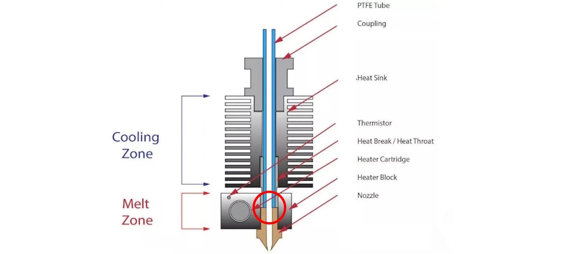
The Hotend is the part of an FDM 3D printer that deals with the melting and deposition of molten plastic material. A Hotend consists of a Nozzle that deals with depositing the molten material, a Heatblock that deals with the melting of the material and a Heatbreak that keeps the hot zone separate from the cold zone of the Hotend. The Heatbreak can be equipped with a heat sink, which in turn is equipped with a fan.

When assembling a Hotend, care must be taken to ensure that the PTFE tube is in beating with the Nozzle. This implies that the PTFE tube is inserted inside the Heatbreak, then the filament flows inside the PTFE tube and reaches the Nozzle directly, without intermediate zones; therefore, it is essential that the PTFE is tightly tightened and joined to the Nozzle, so that the filament flows forcibly through the exit hole of the Nozzle. In the event that there is even a slight gap between PTFE and Nozzle, then leakages of molten filament from the top edge of the Heatblock can occur, causing fillings and damage to both the print and the printer.

TCHC TR6 Anti Leakage Hotend

In addition, the PTFE tube, in the part in contact with Nozzle and Heatblock, tends to reach the same melting temperature set for the filament, however this is not a problem as PTFE supports temperatures up to 300C very well before melting, well beyond the normal printing temperatures of PLA, PETG and ABS. On the other hand, the higher the printing temperature, the greater the amount of heat that the Heatbreak must dissipate; in fact, when the heat is not dissipated properly, it tends to rise inside the PTFE causing the filament to melt in areas far from the nozzle, resulting in obstructions that prevent the filament from passing. In addition, the PTFE tube inside the Heatbreak also begins to lose its characteristics, thus causing obstructions. For this reason, it is necessary to accompany the Heatbreak with a heatsink with fan, in this way the passage of heat is quickly interrupted.

TCHC TR6 Anti Leakage Hotend 1

To solve these two problems, you can switch to a Hotend like the Hotend Trianglelab TCHC TR6 Model B, which is a Hotend with Bi-Metal thin wall Heatbreak; in this way the PTFE tube is not in contact with the hot Nozzle, but stops high in the Heatsink, where the temperature is cold. Therefore, the filament passes from PTFE to Bi-Metal thin wall Heatbreak when it is still solid, and so leakages of molten material cannot occur. In addition, the Bi-Metal thin wall Heatbreak is welded inside the Nozzle already factory, and therefore it is not possible for losses of molten material between the Bi-Metal thin wall Heatbreak and the Nozzle.

TCHC TR6 Anti Leakage Hotend 2

With this type of Hotend it is therefore possible to definitively solve two problems that afflict users of a 3D printer, namely the leakage of molten material between PTFE and Nozzle, and the deformation of the PTFE tube due to the high temperatures reached during the printing of materials such as PETG / ABS / NYLON.

TCHC TR6 Anti Leakage Hotend 3

The Hotend Trianglelab TCHC TR6 Model B is the same size as the Hotend MK8 of the Longer FDM 3D printers, so the installation is very user friendly and plug & play. The new Hotend fits both the Longer Classic Printhead and the new Longer Dual Blower, although the Longer Dual Blower is recommended as it provides greater heat dissipation of the Heatsink, as it has a much larger fan than normal. For installation, simply remove the print head cover and the fans, then just unscrew the old Hotend MK8 and screw the new Hotend TCHC TR6 Model B. Instead, as regards the connection of the cables, simply connect the two white cables of the heating resistor to the HEATER port on the mainboard, instead or two black cables of the temperature sensor must be connected to the TH port of the mainboard. The most skilled and experienced users can simply cut the cables of the old Hotend and solder them to the cables of the new Hotend.

TCHC TR6 Anti Leakage Hotend 4

Once the assembly and calibration procedures have been completed, you can immediately proceed with printing. You may need to reduce the retraction values inside the slicer and adjust small settings, however 3D printing will be much easier and more enjoyable thanks to this anti-leakage and PTFE-free Hotend in the hot zone.

By Academy | October 8, 2023
Mesh Bed Levelling for LK4PRO & LK5PRO - LONGER
Mesh Bed Levelling for LK4PRO & LK5PRO

LO 

Some users of Longer FDM printers prefer to use a BL-TOUCH automatic leveling system in order to obtain more precise and higher quality prints, as well as making the printing bed leveling process easier and more immediate.

However, the standard automatic leveling procedure is for the BL-TOUCH sensor to remeasure the plane points before each new print. This procedure takes time, and is often useless, especially in the case of making daily prints, the print bed maintains calibration and the printer is never moved. If these conditions are met, then you can simply recall a previous plan mesh before starting a new print, without the need to create a new one.

If you want to print using the last saved mesh, simply change the START GCODE for BL-TOUCH to the following START GCODE:


-- BL-TOUCH START GCODE --
G21 ; metric values
G90 ; absolute positioning
M82 ; set extruder to absolute mode
M107 ; start with the fan off
; confirm BL-touch safety
M280 P0 S160 ; BL-Touch Alarm release
G4 P100 ; Delay for BL-Touch homing
G28 X0 Y0 ; move X/Y to min endstops
G28 Z0 ; move Z to min endstops
; reconfirm BL-touch safety
M280 P0 S160 ; BL-Touch Alarm realease
G4 P100 ; Delay for BL-Touch
; bed leveling
M420 S1 Z5 ; enable bed leveling
; prepare hot-end
G92 E0 ; Reset Extruder
G1 Z2.0 F3000 ; Move Z Axis up little to prevent scratching of Heat Bed
G1 X0.1 Y20 Z0.3 F5000.0 ; Move to start position

G1 X0.1 Y150.0 Z0.3 F1500.0 E15 ; Draw the first line

G1 X0.4 Y150.0 Z0.3 F5000.0 ; Move to side a little

G1 X0.4 Y20 Z0.3 F1500.0 E30 ; Draw the second line

G92 E0 ; Reset Extruder

G1 Z2.0 F3000 ; Move Z Axis up little to prevent scratching of Heat Bed

G1 X5 Y20 Z0.3 F5000.0 ; Move over to prevent blob squish
; -- end of BL-TOUCH START GCODE -- 


In this way, printing will start immediately, without mesh the print bed, using the last calibration made. However, sometimes you will need to create a new mesh, especially if the print plate has been moved or if the printer has been moved; in this case, simply create open "Notepad" on your laptop and paste the following GCODE:

; bed leveling
G28 X0 Y0 ; move X/Y to min endstops
G28 Z0 ; move Z to min endstops
G29; Auto leveling
M500 ; save data of G29 and M420
M420 S1 ; enable bed leveling

For last, save the file as levelling.gcode (be careful, do not save as .txt) and copy the GCODE you just created into the microSD of your printer. Whenever it will be necessary to calibrate the printing plate, simply start the GCODE from the printer display, like any other print file, and wait for the measurement to complete.


By Academy | August 23, 2023
BL-Touch Installing Guide for LK4PRO & LK5PRO - LONGER
BL-Touch Installing Guide for LK4PRO & LK5PRO

Longer LK4PRO & LK5PRO are two FDM printers capable of producing high-quality 3D prints. However, you can increase the ease and quality of printing by installing a BL-TOUCH or 3D-TOUCH compatible automatic leveling sensor.


Preparation

Wiring

  1. Switch-off the printer
  2. Find the position of motherboard, then screw down the mainboard cover
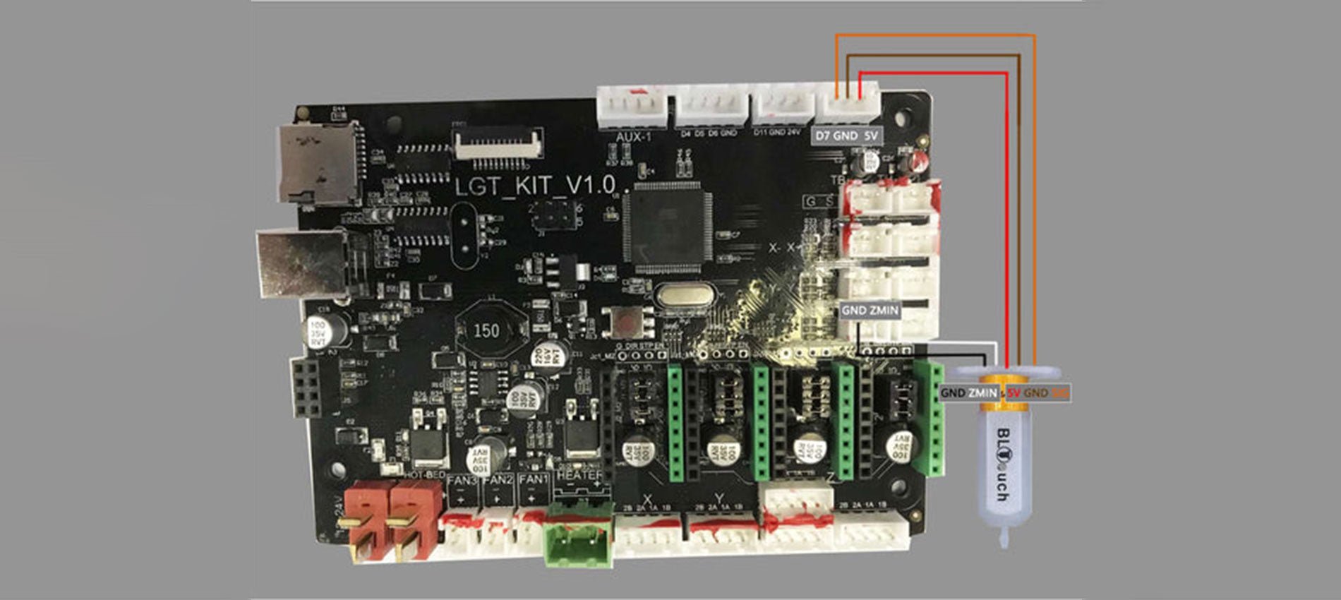
  3. Unplug the Z-MIN wire (2-pin) from the mainboard
  4. Connect the sensor's cables to the motherboard, as the picture below shows.
    Connect the sensor's cables to the motherboard
  5. Screw up the mainboard cover
  6. Remove the Z endstop switch, as picture showing below
    Remove the Z endstop switch
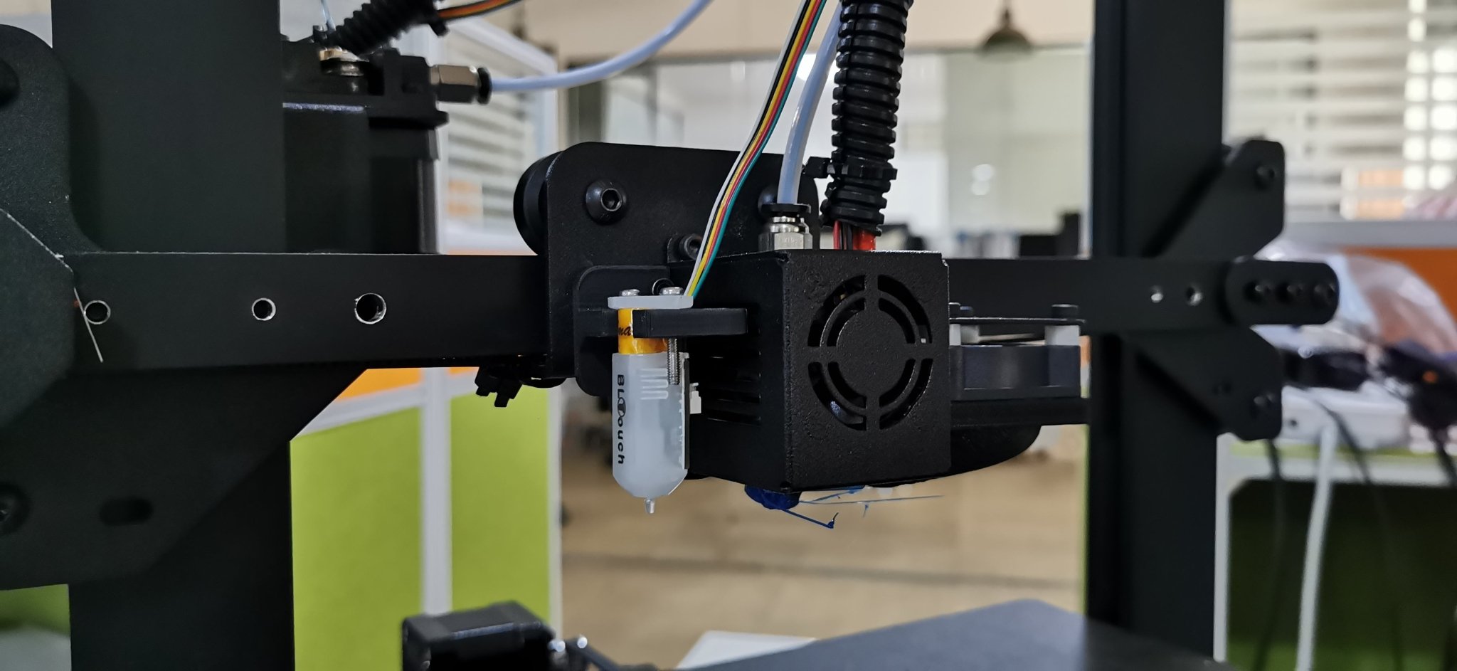
  7. Screw down the left 2 screws of the printhead module and mount the BL-TOUCH as picture showing below (follow the same step if you have DualBlower)
    Screwdown left 2 screws of PrintHead module and mount the BL-TOUCH

Configuration

  • Confirm BL-TOUCH wiring and mounting is complete
  • Power ON the printer
  • Connect PC and printer with the modified USB cable.
  • Open Pronterface software, select serial port (115200 baudrate) and connect it to the printer

Adjusting Z-Offset

  1. Clean up bed and nozzle, and ensure no materials stick on 
  2. Send M851 Z0 to reset Z offset value.
  3. Send G28 to home XYZ axis
  4. Send G1 F60 Z0 to lower Z axis to the software origin. 
  5. Send M211 S0 to inactivate software endstop function
  6. Place a sheet of paper (0.10 mm approximately) on the bed and use Pronterface to lower the nozzle 0.1 mm by 0.1 mm until you feel friction between the nozzle and the sheet of paper (the paper is not to be jammed but not too free either). Then remove the sheet
  7. Send M114 to get the current Z height value (usually negative) and take note of it. This is the z-offset value we need
  8. Send M851 Z-x.x to set z-offset. (x.x is the value of previous value; for example, if previous value is -1.2, then send M851 Z-1.2.)
  9. Send M500 to save current settings
  10. Send M211 S1 to reactivate software endstop function. 
  11. Send G28 to home XYZ axis
  12. Send G1 F60 Z0 to test if the Z axis could go back to the actual Z origin by checking the clearance between the bed and the nozzle if it is about 0.1 mm (the thickness of a sheet of paper). If not, please repeat steps from 1 to 11.

START GCODE replacement

Inside the Slicer software (Cura, Slic3r, Simplify3D), replace the original START GCODE with the following START GCODE for BL-TOUCH.

-- BL-TOUCH START GCODE --
G21; metric values
G90: absolute positioning
M82: Set extruder to absolute mode
M107: start with the fan off
; confirm BL-touch safety
M280 P0 S160 ; BL-Touch Alarm release
G4 P100 ; Delay for BL-Touch homing
G28 X0 Y0 ; move X/Y to min endstops
G28 Z0 ; move Z to min endstops
; reconfirm BL-touch safety
M280 P0 S160 ; BL-Touch Alarm Release
G4 P100 ; Delay for BL-Touch
; bed leveling
G29: Auto leveling
M420 Z5 ; set LEVELING_FADE_HEIGHT
M500: save data of G29 and M420
M420 S1 ; enable bed leveling
; prepare hot-end
G92 E0 ; Reset Extruder
G1 Z2.0 F3000 ; move the Z Axis up little to prevent scratching of the heat bed.
G1 X0.1 Y20 Z0.3 F5000.0 ; Move to start position

G1 X0.1 Y150.0 Z0.3 F1500.0 E15 ; Draw the first line

G1 X0.4 Y150.0 Z0.3 F5000.0 ; Move to side a little

G1 X0.4 Y20 Z0.3 F1500.0 E30 ; Draw the second line

G92 E0 ; Reset Extruder

G1 Z2.0 F3000 ; move the Z Axis up little to prevent scratching of the heat bed.

G1 X5 Y20 Z0.3 F5000.0 ; Move over to prevent blob squish
; -- end of BL-TOUCH START GCODE -- 

By Academy | August 23, 2023
Lens Cleaning for Longer Ray5 10W

Longer Ray5 10W has a laser module capable of engraving and cutting multiple types of materials. However, depending on the type of work that is carried out, it is possible that a fair amount of smoke is produced, which can inevitably settle on the lens of the laser module and therefore blur it. Once the lens of the laser module is dirty or clouded, the laser beam can no longer pass through it, and therefore the emission of the laser module is drastically reduced. As a consequence, more and more power will be needed to engrave the same materials already engraved previously, until it will be practically impossible to engrave any type of material, even setting 100% power. This problem occurs most when an air assist system is not used; in fact, an air assist system allows you to create air pressure in the vicinity of the lens, thus preventing smoke and dust from settling easily on the lens.

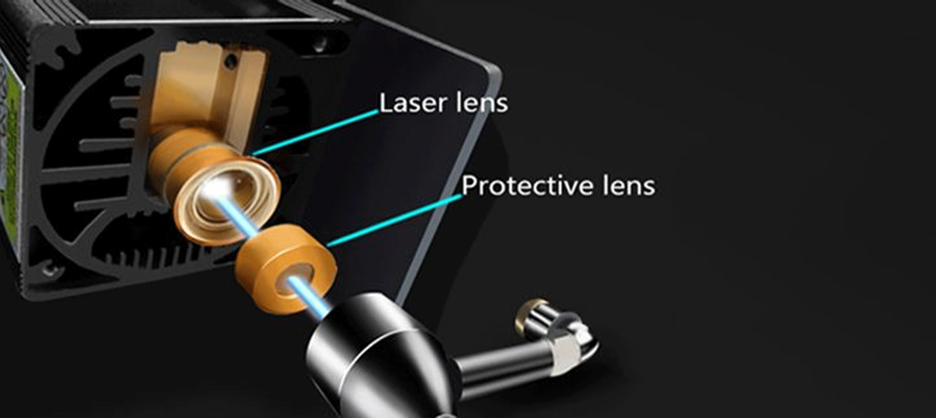
Laser lens and Protective lens

In order to solve this problem, it is necessary to proceed to cleaning the lens of the laser module; once the lens is cleaned, the laser beam can pass through it without suffering losses, and therefore the materials will be engraved or cut again to perfection.

To proceed with the cleaning of the lens of the laser module of Longer Ray5 10W, it is necessary first to completely disassemble the laser module, as shown in the figure:

completely disassemble the laser module

The laser module of the Longer Ray5 10W has a factory-installed protective lens, which can be unscrewed and cleaned separately from the laser module. This lens is a simple protective glass and has no focusing function. After removing the protective lens, you can proceed to clean the lens with the use of a cotton swab soaked in alcohol. Be careful to prevent alcohol from entering the inside of the lens.

completely clean and free of dirt

Use one or more cotton swabs soaked in alcohol until the lens is completely clean and free of dirt; at this point, therefore, you can proceed to screw it to the laser module and reassemble the laser module of Longer Ray5 10W. At the end of the cleaning procedure, you can proceed to engrave a sample file contained in the microSD card of Longer Ray5 10W so you can evaluate the total restoration of the functionality of the laser module.

By Academy | July 25, 2023
Lens Cleaning for Longer Ray5 5W - LONGER
Lens Cleaning for Longer Ray5 5W

Longer Ray5 5W has a laser module capable of engraving and cutting multiple types of materials. However, depending on the type of work that is carried out, it is possible that a fair amount of smoke is produced, which can inevitably settle on the lens of the laser module and therefore blur it. Once the lens of the laser module is dirty or foggy, the laser beam can no longer pass through it, and therefore the emission of the laser module is drastically reduced. As a consequence, more and more power will be needed to engrave the same materials already engraved previously, until it will be practically impossible to engrave any type of material, even at 100% power.

In order to solve this problem, it is necessary to proceed to cleaning the lens of the laser module; once the lens is cleaned, the laser beam can pass through it without suffering losses, and therefore the materials will be engraved or cut again to perfection.

To proceed with the cleaning of the lens of the laser module of Longer Ray5 5W, it is necessary to first completely disassemble the laser module, as shown in the figure:

The laser module of the Longer Ray5 5W has a factory-calibrated lens, so be careful not to unscrew or screw on the lens. Otherwise, the focus will be lost irreparably. Once the lens is accessible, with one hand you have to hold the whole laser module upside down, while with the other you can proceed to clean the lens with the use of a cotton swab soaked in alcohol. Be careful to prevent alcohol from entering the laser module.

Use one or more cotton swabs soaked in alcohol until the lens is completely clean and free of dirt; at this point, therefore, you can proceed to reassemble the laser module of Longer Ray5 5W. At the end of the cleaning procedure, you can proceed to engrave a sample file contained in the microSD card of Longer Ray5 5W so you can evaluate the total restoration of the functionality of the laser module.

By Academy | July 25, 2023
Text Layout Cutting with Lightburn and Longer Ray5 - LONGER
Text Layout Cutting with Lightburn and Longer Ray5

Longer Ray5 allows you to engrave and cut multiple types of materials. In particular, many users of Longer Ray5 prefer to create a custom text and then engrave or cut it on wood panels or similar material. Engraving a text using the laser beam is not a big problem, as it is sufficient to set the right parameters for the type of material chosen, and the result will be excellent. However, if you want to cut (e.g., on wood or paper) your custom text, then setting the right parameters may not be enough.

In fact, depending on the type of text chosen, it may be necessary to make manual changes to the text so that the cut can take place correctly. Analyzing the issue in detail, assuming you want to laser cut the word "NICE," then there is no problem; however, if the word is "HELLO," then it should be noted that the letter "O" consists of a closed surface, which when cut will fall away from the material and thus change the layout of the letter "O."

Specifically, this problem occurs with all letters that contain a closed surface within them, such as the letters "A – B – D – O – P – Q – R."

Using LightBurn software, you can solve this problem really easily and quickly. In detail, first you proceed with the creation of your own personalized text within LightBurn. After entering the text, you will visually check for any letters that have problems when cutting.

In the example given here, there are some letters that cannot be cut correctly and therefore need to be corrected first. The solution to this problem lies in eliminating the closed surface inside the letter: to do this, just create a "bridge" that connects this closed surface with the rest of the letter.

In this way, after making the cut, this closed surface will remain attached to the cut panel, and therefore the layout of the letter will not be changed.

In particular, you must manually create a small rectangle, which must be pasted inside each problematic letter in order to create a bridge between the closed surface of the letter and the letter itself, as shown in the example below. After that, you have to make a Boolean subtraction between the letter and the rectangle.

We proceed to insert a rectangle for each letter that needs to be corrected, then we proceed with the subtraction (the procedure must be repeated for each letter, one letter at a time). Finally, the end result will look like this:

At this point, you can make a cutting preview or proceed with the export of the G-code on the microSD of Longer Ray5 and perform the cut (always remembering to set the correct parameters first to be able to cut the type of material chosen).

This technique can also be applied when using different text layouts, such as italic text or number format, so that you always eliminate any closed surfaces that prevent you from making a correct laser cut.

By Academy | July 6, 2023
Engraving & Cutting with Lightburn and Longer Ray5 - LONGER
Engraving & Cutting with Lightburn and Longer Ray5

Longer Ray5 allows you to engrave and cut multiple types of materials. In particular, many users of Longer Ray5 prefer to carry out engraving and cutting work at the same time, especially when it comes to working with wood panels; however, engraving and cutting do not necessarily have to be two distinct processes, as using Lightburn, you can perform both machining operations in one operation.

In particular, after opening an image in LightBurn, proceed to set the engraving parameters in the window on the right of the screen. I know that the engraving parameters are those of the model image.

After setting the engraving parameters, right-click with the mouse on the imported image, then select Trace Image.

In the screen that opens, define the quality of the cutting perimeter by increasing or decreasing the Threshold value, then confirm by pressing OK.

The image will be superimposed by a perimeter, as set in the previous screen, and at the same time in the window on the right of the screen will appear a new entry relating to the cut to be made, indicated with Model Line. For Model Line, set image cropping parameters, such as speed, power, and number of passes.

At the end, press Save Gcode to export the working file to the microSD of Longer Ray5, then proceed to start working on Longer Ray5. Alternatively, before exporting the GCode, you can check the simulation of the engraving and cutting process by pressing Preview.

In this way, Longer Ray5 will engrave the selected image, after which it will cut the image following the perimeter set above.


Above is the introduction of the first layer calibration; I hope it can help you. If you still have any questions during the operation, please visit our Support Page. Our knowledgeable staff is happy to assist you and your team with any questions.

Want to learn more about RAY5 Laser Engraver? Check out the video below.

https://www.youtube.com/playlist?list=PLLz1z_0pXsW0rjYbC2V_upO1YlU4HeuAg

Step into a world of precision craftsmanship with LONGER RAY5 Series. These high-accuracy laser engravers and cutters redefine what's possible, effortlessly mastering materials with unparalleled precision and ease. Whether you seek to infuse your home with personalized charm or elevate your professional projects, these versatile machines seamlessly adapt to your needs. Their compact design makes them an excellent choice for home laser engravers and cutters, adding a touch of sophistication to your creative space. Meanwhile, their precision engineering makes them equally at home in the professional arena, where they serve as the quintessential desktop laser cutter, providing industrial-grade precision right at your fingertips. Explore limitless possibilities and unlock your creativity with Longer RAY5 Series.

By Academy | June 19, 2023
Material Testing for Longer Ray5 10W & 5W - LONGER
Material Testing for Longer Ray5 10W & 5W

Longer Ray5 5W and Longer Ray5 10W allow you to engrave and cut different types of materials, quickly and easily. However, for each type of processing it is necessary to set different parameters regarding power and speed, precisely because each type of material reacts differently to the laser beam.

To have a reference about what power and speed to adopt for each type of material, there is a fairly complete table accurately reporting the best parameters to use.

about what power and speed to adopt for each type of material

However, the table can only be understood as a general reference; in fact, assuming you want to cut the basswood with Longer Ray5 10W, the recommended parameter is 100% power & 350 mm/min speed, but there are various types of basswood, and each one reacts differently during cutting, so it is not said that these parameters are perfect for each type of basswood, since some basswood could be burned instead of simply cut or not cut at all.

In order to obtain the correct parameters for the type of basswood you intend to cut, Lightburn has a powerful material test tool, which allows you to quickly determine the most specific and correct parameters. From the Lightburn home screen, select Laser Tools – Material Test; this screen will open:

select Laser Tools – Material Test

First, set the Count value to 5 for Vertical and Count to 4 for Horizontal; Also, set Height and Width to 5.00 mm.

Since the recommended parameters for cutting the basswood are 100% power & 350 mm/min speed, you can set a range between 100 and 500 mm/min for speed and a range between 50% and 80% for power (so as to avoid stressing the laser with 100% power).

Next, proceed with Edit Text Setting:

Edit Text Setting

This screen is used to engrave the labels of the test table. Since it is an engraving, set 3000 mm/min speed and 50% Power; Also, set Mode Fill.
Confirm by pressing OK.

At this point, proceed with Edit Material Settings:

Edit Material Settings

In this screen you can set the method of processing the material; since it is a matter of cutting, select Mode Line, and possibly set Number of Passes to 1 or more.
Confirm by pressing OK.

Once back on the main screen, press Save Gcode to export the test file, copy it to the microSD, and start testing on Longer Ray5.

When Ray5 has completed the job, reviewing the table will help you determine which parameters are best to set.


Similarly, if you want to proceed with an engraving test instead of cutting, open the Material Test screen. Since the recommended parameters for engraving the basswood are 35% Power & 3000 mm/min speed, set the testing range as shown in the image below:

set the testing range

On the Edit Material Settings screen, since this is an engraving, select Mode Fill:

the Edit Material Settings screen select Mode Fill

Once back on the main screen, press Save Gcode to export the test file, copy it to the microSD and start testing on Longer Ray5.

When Ray5 has completed the job, reviewing the table will help you determine which parameters are best to set.


Note that, before exporting the Gcode, both for a cut test and for an engraving test, you can always select Preview, which allows you to see in advance how the final result will look.


Lightburn Preview

Above is the introduction of parameter settings and material testing , hope it can help you. If you still have any questions during the operation, please visit our Support Page. Our knowledgeable staff is happy to assist you and your team with any questions.


The Longer Laser RAY5 Series is capable of engraving a wide range of materials, including plywood, basswood, hardwood, pinewood, acrylic, kraft paper, stainless steel, aluminum alloy, ceramics, and more. Additionally, the Longer RAY5 can cut materials such as basswood, acrylic, bamboo, kraft paper, and more.


With its powerful engraving and cutting capabilities, it transcends boundaries to become the best engraving machine and the best laser cutter for a variety of materials. Seamlessly transition from a wood laser cutter to a metal laser engraver, or even become a master jewelry engraver. Discover boundless, unlimited potential with the Longer Laser RAY5 Series.

By Academy | May 30, 2023
Air Assist Kit installation for Longer Ray5 10W & 5W - LONGER
Air Assist Kit installation for Longer Ray5 10W & 5W

Visible light and laser beam have in common the same nature, as both are composed of photons, however the difference between them is in the fact that visible light has an optically isotropic propagation (that is, it propagates identically in all directions) while in the laser all the energy is concentrated within a single beam of very small section. Therefore, when the laser hits matter, it is instantly able to radiate a great power in a very small area, causing a sudden and rapid increase in temperature that alters the state of matter.

Laser engraving machines, such as Longer Ray5, are able to emit a laser beam that instantly transforms the state of matter by combustion, and the contrast between the laser-subjected surface and the surrounding surface creates the visual effect commonly called Laser Engraving. However, the energy hitting a single point is not limited to that point, but the heat generated is also transmitted to the areas surrounding the point, causing the typical burning effect of laser processing.

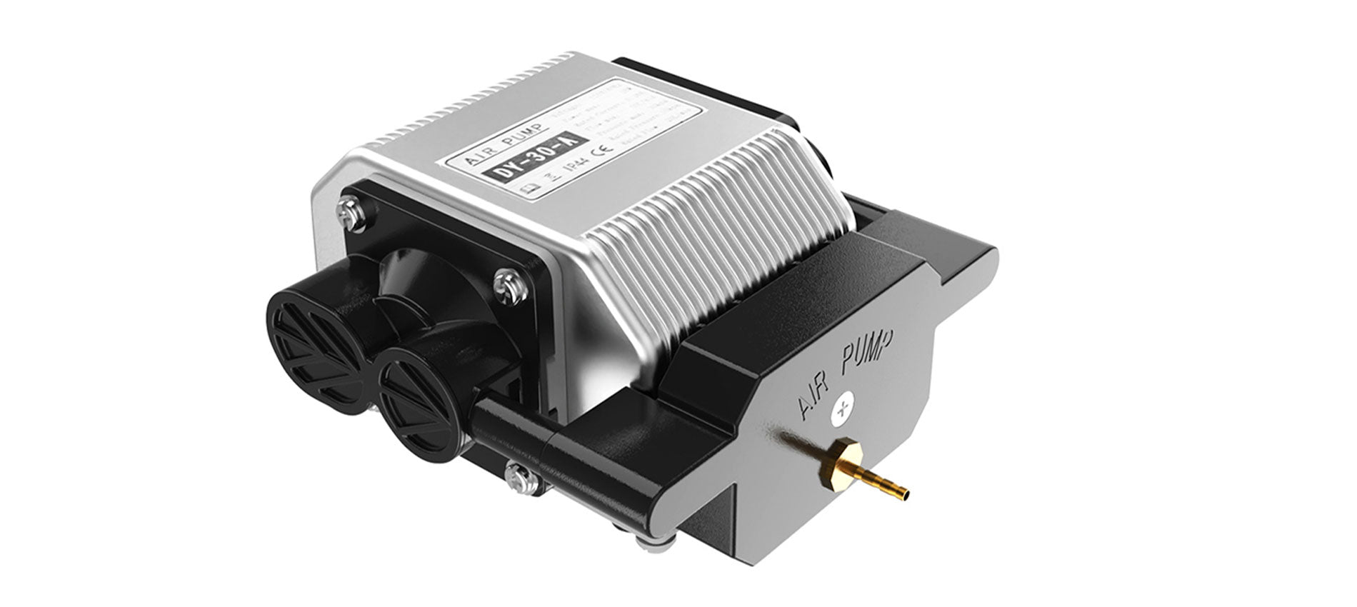
In order to avoid or reduce this effect, an air assist mechanism can be used, which consists of a compressor capable of continuously blowing pressurized air directly onto the area subjected to the laser. In this way, the heat exchanged between the laser area and the surrounding area is mitigated by the fresh air of the Air Assist compressor, thus avoiding the burnt effect around the laser engraving. In addition, the air blown on the engraving zone cancels the heat exchange with the surrounding areas but does not damage the engraving ability of the laser beam. A simple example to understand this phenomenon can be this: if on a summer day with the sun high in the sky you go to the sea, if there is wind, then you feel cool, while if there is no wind, then you feel hot, but in both cases the sun causes burns to the skin in the same way.


Longer Ray5 10W Air Assist installation

The longer Ray5 10W has an official Air Assist kit that consists of two parts, the nozzle kit and the air compressor, available at the following link: https://www.longer3d.com/products/air-assist-set .

Installing the Longer Air Assist on the 10W laser module is really easy; just follow the steps below:

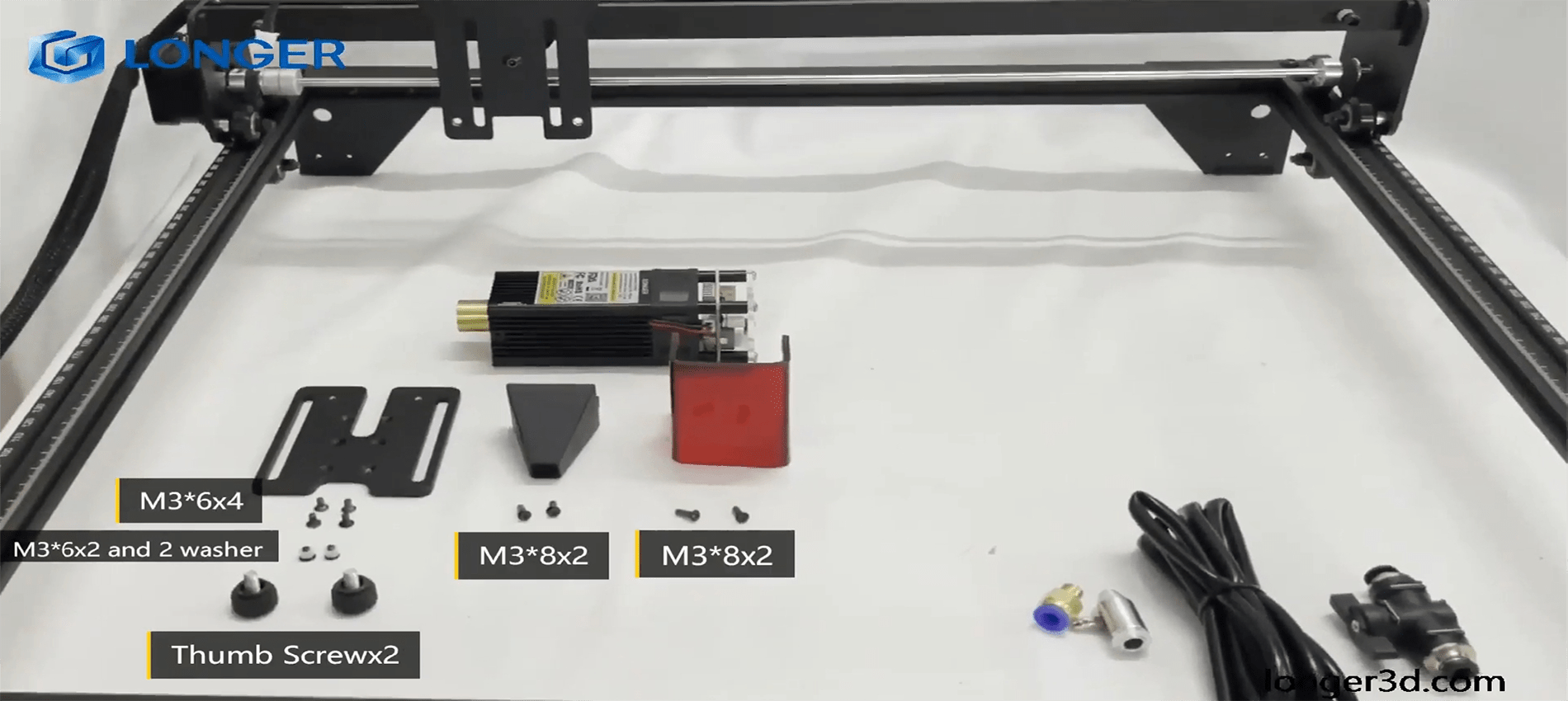
  • First, proceed to disassemble the laser module from the rest of the machine


  • Install the metal nozzle on the laser module


  • Connect a rubber hose between the metal nozzle and the pressure regulator, and connect another part of the rubber hose to the regulator inlet


  • Connect the inlet pipe of the regulator to the outlet of the air compressor


    • Finally, install the laser module on the Ray5, activate the compressor switch and start an engraving from the Longer Ray5 display


Longer Ray5 5W Air Assist installation

To proceed with the installation of the Air Assist kit on the Longer Ray5 5W, it is necessary to purchase, as for the 10W version, the kit consisting of the nozzle kit and the air compressor, available at the following link: https://www.longer3d.com/products/air-assist-set . However, the metal nozzle included inside the kit is compatible with 10W module only; therefore, it is necessary to have a 3D printer to print with PLA or PETG the following nozzle:https://www.thingiverse.com/thing:5585296 .


Installing the Longer Air Assist on the 5W laser module is really easy; just follow the same steps as the installing method for the 10W laser module, but install the 3D-printed nozzle on the laser module instead of the metal nozzle. After that, as mentioned, just follow the same steps as shown for installation on the 10W module.


Conclusions

The use of air assist not only increases the engraving quality but can also increase the laser's cutting capacity thanks to the possibility of removing smoke and combustion debris thanks to the continuous breath of air; without air assist, these would end up settling on the laser lens, hindering the output laser beam of the module. Whether for hobbyist or professional use, Longer Air Assist is absolutely recommended if you want to achieve the maximum performance offered by Longer Ray5 10W and Longer Ray5 5W.

https://www.longer3d.com/collections/laser-engraver

By Academy | May 9, 2023