Turning a flat image into a printable 3D object is one of the most exciting entry points into 3D printing. In this beginner-friendly guide, you will learn how to transform a 2D image into a 3D model using a simple workflow that prepares your image for 3D printing and STL export.
Whether you want to create personalized decorations, lithophanes, signs, or artistic relief models, this tutorial walks you through the complete process step by step.
Table of Contents
Quick Answer
To transform a 2D image into a 3D model, you first prepare a high-contrast image, import it into compatible 3D software, convert it into a height map or relief model, then export the final result as an STL file for 3D printing.
This method is commonly used for lithophanes, engraved artwork, decorative panels, logos, and custom gifts.

What This Guide Covers
This tutorial explains:
- How to prepare an image for 3D conversion
- How height maps create 3D depth
- How to generate an STL file from a 2D image
- How to prepare the model for 3D printing
- Common troubleshooting methods
- Beginner tips for achieving cleaner results
By the end of this guide, you will understand the full workflow required to create a 3D printable model from a flat image.
Why Transform a 2D Image Into a 3D Model
Converting a 2D image into a 3D model opens up many creative possibilities for makers, designers, hobbyists, and small businesses.
Benefits include:
- Creating personalized gifts
- Producing custom lithophanes
- Designing engraved wall art
- Turning logos into printable objects
- Making relief sculptures from photos
- Creating decorative nameplates and signs
This process is especially useful for users who are new to 3D modeling because it reduces the need for advanced CAD design skills.
If you are also learning laser engraving workflows, you may find it helpful to explore related tutorials from LONGER Official Website.
Before You Start
Requirements
Before starting the 2D to 3D model tutorial, prepare the following:
Hardware
- A computer capable of running 3D modeling software
- A 3D printer (optional for physical printing)
Software
- Image editing software
- 3D model generation software
- Slicing software for STL preparation
Follow official machine specifications or instructions.
Recommended Image Types
Best results usually come from:
- Black-and-white images
- High-contrast graphics
- Logos
- Portraits with clear lighting
- PNG or JPG files
File Types
Common export formats include:
Precautions
Before converting an image to a 3D model, keep these important points in mind:
Use High-Contrast Images
Low-contrast images may create uneven or unclear depth details.
Avoid Excessive Background Detail
Busy backgrounds can generate unwanted surface noise in the final model.
Check Image Resolution
Very small images may appear pixelated after conversion.
Verify Printable Thickness
Thin model sections may fail during 3D printing.
Follow Official Printer Settings
Always follow official machine specifications or instructions when preparing print settings.
For additional print preparation guidance, you can review the slicing tutorials available on LONGER Support Center.
Step-by-Step Tutorial
Step 1: Prepare Your 2D Image
Action
Choose and prepare the image you want to convert into a 3D model.
The image should be:
- Clear
- High resolution
- High contrast
- Properly cropped
If necessary, remove unnecessary background elements and improve contrast using image editing software.
Expected Result
You should have a clean image that clearly separates light and dark areas.
Important Notes
- Black areas are often interpreted as lower regions.
- White or brighter areas are often interpreted as higher regions.
- Complex gradients may create uneven surfaces.
If you are creating engraved artwork, you may also benefit from reading image optimization tutorials on LONGER Academy.
Step 2: Import the Image Into the Software
Action
Open your chosen 3D generation software and import the prepared image file.
Most software tools provide an image import or height map function that converts brightness values into elevation data.
Expected Result
The software should display the imported image and prepare it for 3D conversion.
Important Notes
- Ensure the image is correctly oriented before generating the model.
- Some software may automatically invert brightness values.
- Double-check preview settings before continuing.

Step 3: Convert the Image Into a Height Map
Action
Use the software’s height map or relief generation feature to convert the 2D image into 3D geometry.
The brightness of the image determines the depth of the generated surface.
Expected Result
A preview of the raised or recessed 3D surface should appear.
Important Notes
- Higher contrast usually produces clearer depth separation.
- Excessively detailed images may generate rough surfaces.
- Small adjustments can significantly affect the final appearance.
Understanding Height Map Conversion
A height map converts brightness into physical depth:
- White areas = higher surfaces
- Black areas = lower surfaces
- Gray areas = intermediate depth
This is one of the most common methods used to create a 3D model from an image.
Step 4: Generate the 3D Model
Action
Generate the final 3D mesh after adjusting the model settings.
Inspect the model carefully in preview mode.
Expected Result
The software should create a complete 3D object that can be rotated and inspected.
Important Notes
Check for:
- Broken geometry
- Missing sections
- Uneven surfaces
- Thin walls
If problems appear, return to the image preparation stage and improve contrast or simplify the design.

Step 5: Export the STL File
Action
Export the completed model as an STL file.
STL is the most commonly used format for 3D printing workflows.
Expected Result
You should obtain a printable STL file ready for slicing.
Important Notes
- Save backup project files before exporting.
- Confirm the export scale before printing.
- Check the model dimensions carefully.
Step 6: Prepare the File for 3D Printing
Action
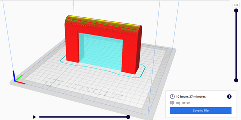
Import the STL file into slicing software and configure the print settings.
Adjust:
- Layer height
- Infill
- Supports
- Orientation
Follow official machine specifications or instructions.
Expected Result
The slicer should generate a printable G-code file.
Important Notes
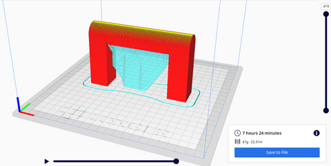
- Model orientation can greatly affect print quality.
- Thin models may require supports.
- Larger relief designs may increase print time significantly.
If you are new to print preparation, you can also explore additional beginner resources from LONGER 3D Printing Guides.
Common Problems and Solutions
| Problem |
Requirements |
Solution |
| Image lacks detail |
High-resolution source image |
Use a clearer and larger image |
| Surface appears rough |
Proper contrast adjustment |
Simplify the image and reduce noise |
| Model contains holes |
Clean geometry |
Recheck image preparation and regenerate |
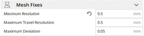
| STL file will not slice |
Valid mesh structure |
Repair the mesh using mesh repair tools |
| Print fails during printing |
Stable print settings |
Verify adhesion and follow official machine specifications |
| Depth looks inverted |
Correct brightness interpretation |
Invert the image colors before conversion |
| Details are too shallow |
Proper height settings |
Increase height map depth gradually |
Tips for Better Results
Use Simple Images First
Beginners should start with logos or black-and-white graphics before attempting detailed portraits.
Increase Contrast Carefully
Higher contrast improves depth separation but excessive contrast can remove subtle details.
Avoid Tiny Features
Very small elements may not print correctly depending on nozzle size and layer height.
Preview the Model From Multiple Angles
Always rotate and inspect the model before exporting the STL file.
Test Print Small Versions First
Printing a smaller prototype can save time and material before creating the full-size model.
Frequently Asked Questions
Q: How do you transform a 2D image into a 3D model?
A: You import a high-contrast image into 3D software, generate a height map or relief surface, then export the result as an STL file for 3D printing.
Q: What is the best image type for converting to a 3D model?
A: High-contrast black-and-white images usually produce the cleanest and most detailed results.
Q: Can I convert a photo into a 3D model for beginners?
A: Yes. Beginner-friendly tools can convert photos into relief-style 3D models using grayscale depth mapping.
Q: What file format is used for 3D printing?
A: STL is the most commonly used file format for preparing 3D printable models.
Q: Why does my 3D model look rough or noisy?
A: Low-quality images, excessive detail, or poor contrast can create rough surfaces during height map conversion.
Q: Can I make a lithophane from an image?
A: Yes. Lithophanes are commonly created by converting grayscale images into varying thickness levels for 3D printing.
Q: Do I need advanced CAD skills for a 2D to 3D model tutorial?
A: No. Many image-to-3D workflows are beginner-friendly and require minimal CAD experience.
Q: What is the best way to create a 3D model from a 2D image?
A: Start with a clean, high-contrast image and use reliable 3D conversion software that supports height map generation.
Final Thoughts
Learning how to transform a 2D image into a 3D model is an excellent way to begin exploring 3D printing and digital fabrication. With the right image preparation and careful workflow setup, even beginners can create impressive relief models, lithophanes, logos, and decorative prints.
Start with simple designs, test your settings carefully, and continue refining your workflow as you gain experience. For additional tutorials, troubleshooting help, and machine-specific guides, explore the resources available on LONGER Official Blog.